
Update 7/14/14: I’ve posted a vertical loudspeaker aiming calculator which is a better starting point than this in most cases
One of the things on which I’ve been working of late is a formula to find the ideal speaker coverage angle for a seating area. It has involved a lot of trigonometry and double checking in MAPP, but I’ve found something which seems to work pretty well for single speaker applications and fits conveniently into an excel calculator:
Introduction
The idea for this formula originally came from Bob McCarthy’s concept of viewing a speaker’s coverage as a ratio between the distance to a given point and width of horizontal coverage at that point. Although in practice there are too many factors acting for a formula dealing with speaker coverage to be completely accurate, the goal of this formula is to yield acceptable results when implemented in the field. The basic relationship between the speaker’s coverage pattern and the plane is easily expressed, but additional trigonometry has been conducted to derive a formula best suited to real venues using the length of the audience plane, the distance from its rear to the speaker, and the distance from its front to the speaker. In addition to insights provided in Bob McCarthy’s book, I would like to extend a thank you to Mauricio Ramirez of Meyer Sound for his advice in the creation of this formula.
Formulation
We begin by considering the coverage of the individual loudspeaker:
 Fig. 1
The speaker’s coverage pattern, which we shall call ϕ, is defined as the angle at which the sound pressure level is 6 dB below the on-axis SPL at the same distance, and is readily learned for a specific loudspeaker from the manufacturer’s literature. R1 is the length of the loudspeaker’s throw in our situation, and the inverse square law tells us that this will be 6 dB lower in SPL than the point at half of distance R1. We will define the distance from on-axis to the speaker’s edge at a distance of half of R1 as y, and the angle between the speaker’s coverage pattern and a distance y as taken from a line parallel to on-axis is equal to half of ϕ. We can find ϕ in terms of y:

We will now consider the audience plane:
 Fig. 2
We will call the length of the audience plane x, and we will place the speaker the same R1 away from the farthest point on the plane, and we will draw y, which is perpendicular to R1, to equal the height of the audience plane. We will call the distance from the speaker to the nearest point on the plane R2. The angle between R1 and R2 will be ϑ, and we can solve for it in terms of R1, R2 and x using the law of cosines:
Applying additional trigonometry, we find y in terms of ϑ:

We substitute these back into our original equation, finding the coverage angle for which y will be equal to the height of the audience plane:

We arrive at the angle ϕ consistent for which the front and back of the audience plane, both lying on or between the –6 dB points in fig.1, receive a near equal sound pressure level.
Analysis
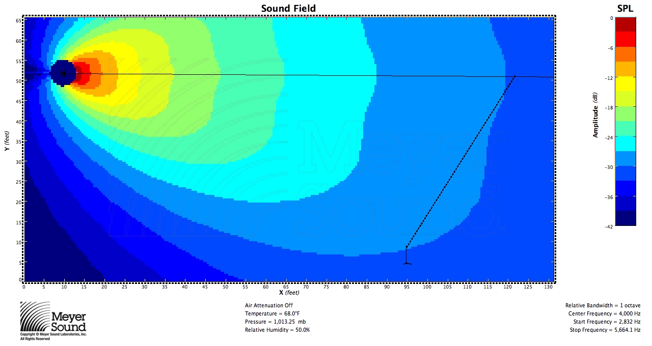
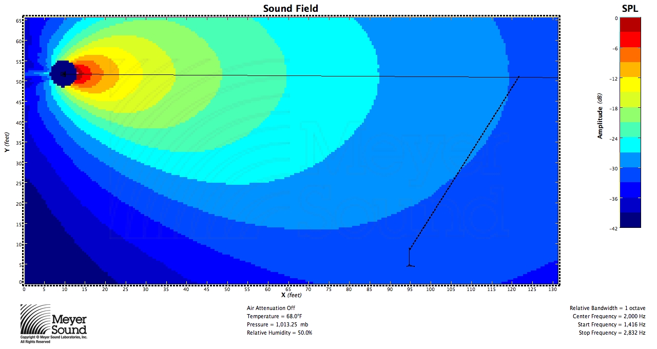
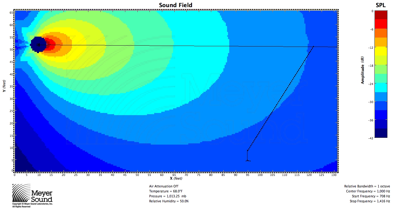
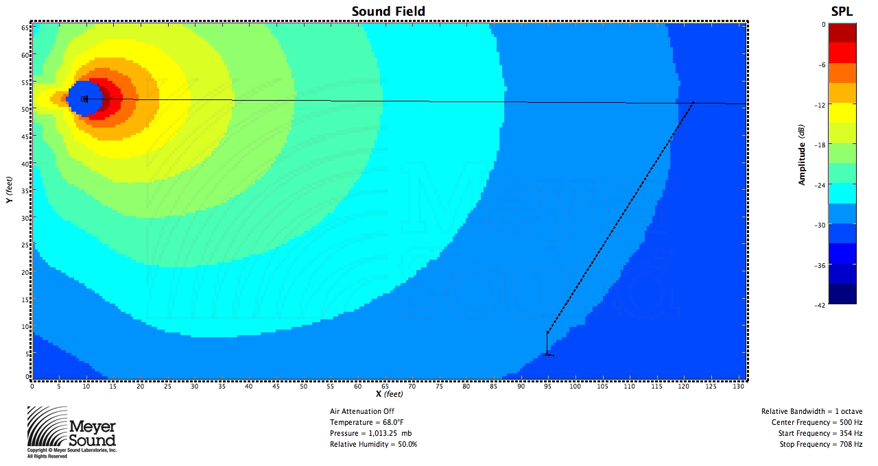
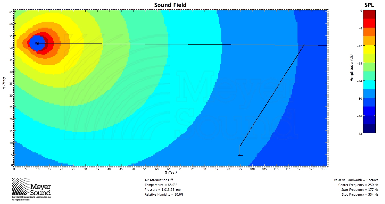
We’ll apply this formula to two scenarios. Scenario 1 with a 50˚ speaker:
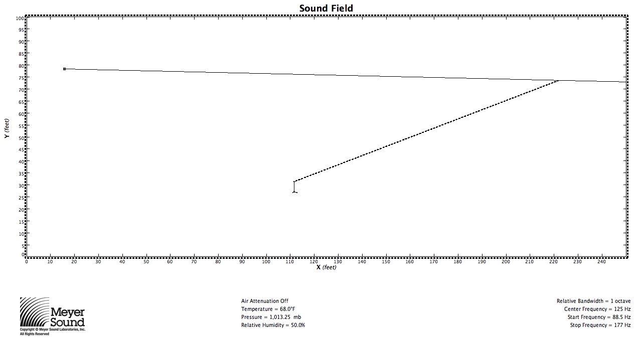
x=118’
R1=207’
R2=108’
ϕ consistent=52˚
Scenario 1 at 8 kHz:

Scenario 1 at 4 kHz:

Scenario 1 at 2 kHz:

Scenario 1 at 1 kHz:

Scenario 1 at 500 Hz:

Scenario 1 at 250 Hz:

Scenario 1 at 125 Hz:

Scenario 2 with a 100˚ speaker:
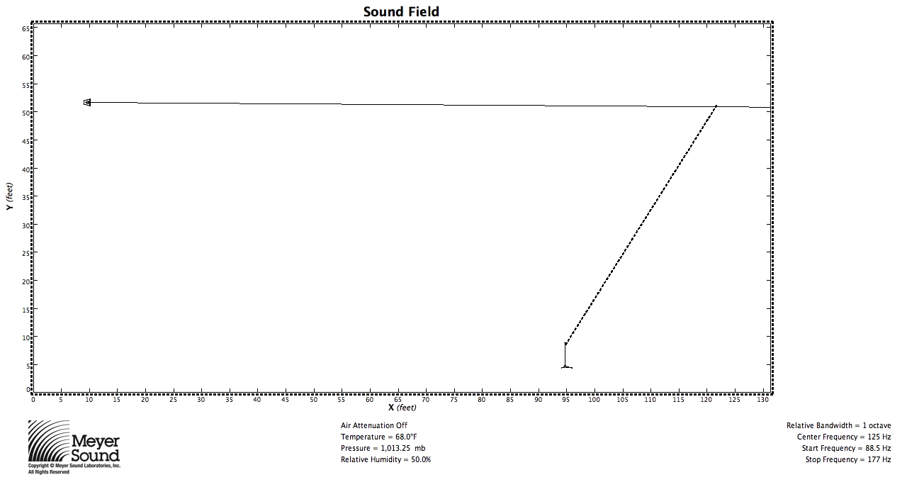
x=50/6’
R1=113′
R2=96′
ϕ consistent=98˚
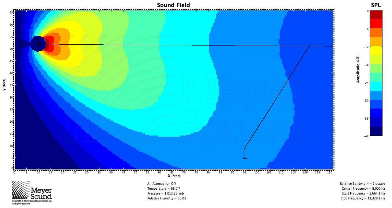
Scenario 2 at 8 kHz:
Scenario 2 at 4 kHz:
Scenario 2 at 2 kHz:
Scenario 2 at 1 kHz:
Scenario 2 at 500 Hz:
Scenario 2 at 25o Hz:
Scenario 2 at 125 Hz:
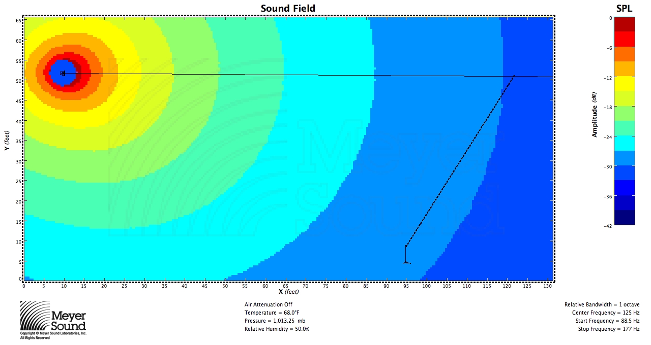
In acoustic simulations of scenarios requiring both wide and narrow speakers, speakers with angles similar to those predicted by the formula provide coverage within ±3 dB as shown by the 3 dB contours in the simulations. As frequency decreases so does the directivity index of the speaker, and the speaker eventually becomes an almost omnidirectional source where coverage consistency adheres merely to the inverse square law.
Conclusion
This formula is an effective way of determining the right speaker for the job. It mathematically determines the coverage angle at which the entire seating plane is within the speaker’s coverage at points that do not vary much in level. Theoretically, for a speaker that perfectly conforms to a coverage pattern with a linear level transition at all frequencies from on-axis to off-axis, a physical impossibility in reality, it is evident that not all of the plane will experience the same SPL as the rear of the plane. The seating plane will fit in the area in figure 1 bound by the -6 dB points, the line between them, and the corner of the coverage here where the level is between -6 dB and -12 dB; therefore, no matter where in the speaker’s coverage the line is, sound level at any frequency will not vary by more than 6 dB in a theoretical situation. When implementing speakers based on this formula in the real world, we will have to accept that we cannot quite achieve this degree of consistency at all frequencies. Note that if R2 equals half of R1, the audience seating plane will be the exact line between the -6 dB points of the speaker’s coverage, and therefore ϑ will equal half of ϕ as both shown figures 1 and 2 and proven in the final formula. If the seating plane extends outside of the -6 dB points, such that R2 is less than half of R1, it is impossible to ensure a variance of less than 6 dB from a single speaker because the inverse square law tells us that the SPL will decrease a significant amount over the length of the plane.
This formula is readily applied to an audience area that is one plane where R2 is more than half of R1, but in practice few audience areas meet this condition and therefore cannot be covered consistently with a single speaker. One instance of a seating plane that frequently does meet this condition is a balcony or mezzanine area (Figure 19). This formula can also be applied to systems with multiple speakers to find the ideal coverage of a delay speaker. This is done by finding the point where consistent coverage of the audience plane from the main speaker system ends, or is more than 6 dB quieter than the loudest point on the plane, and using the formula to determine the right speaker to the cover audience area between this point and the end of the seating plane (Figure 20). This formula also has the potential to be used for several individual speakers in an array of speakers to consistently cover a plane where one speaker will not do, but this will be addressed in a paper of its own.
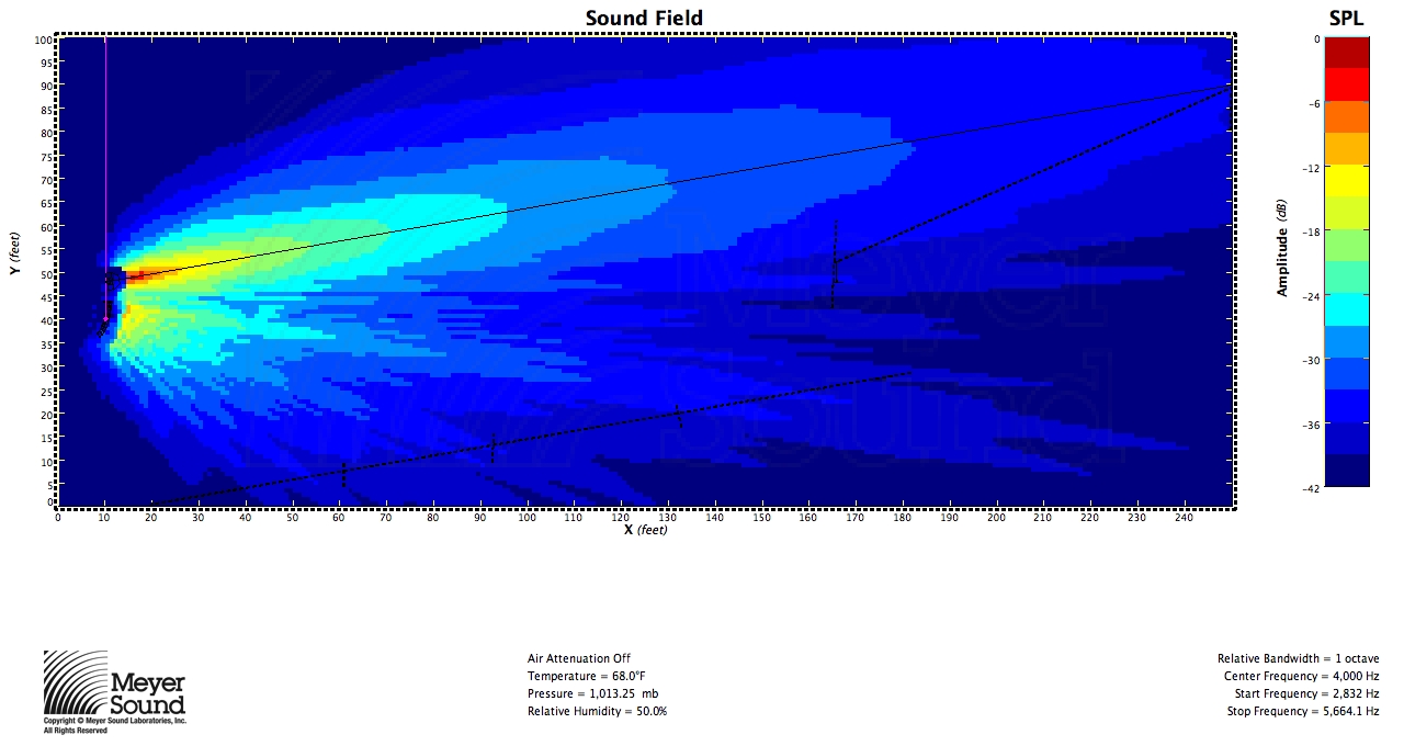 Fig. 19
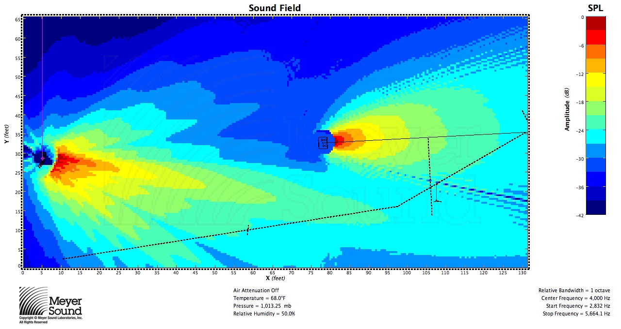
Fig. 20
Another Example (3/9/10)
In response to John’s comment, it is worth pointing out that while mathematically the speaker and the plane can be oriented with any respect to each other, in practice, in order to meet the condition that the shortest distance is more than half of the longest distance, the speaker will often have to be flown as high as possible. Remember, however, that this formula is based on a known speaker position. Below are three examples of the formula used to determine the speaker to cover a balcony: one with the speaker near the top of the listening area, one with the speaker in the middle, and one with the speaker below the listening area. All are MAPP predictions at 8 kHz:
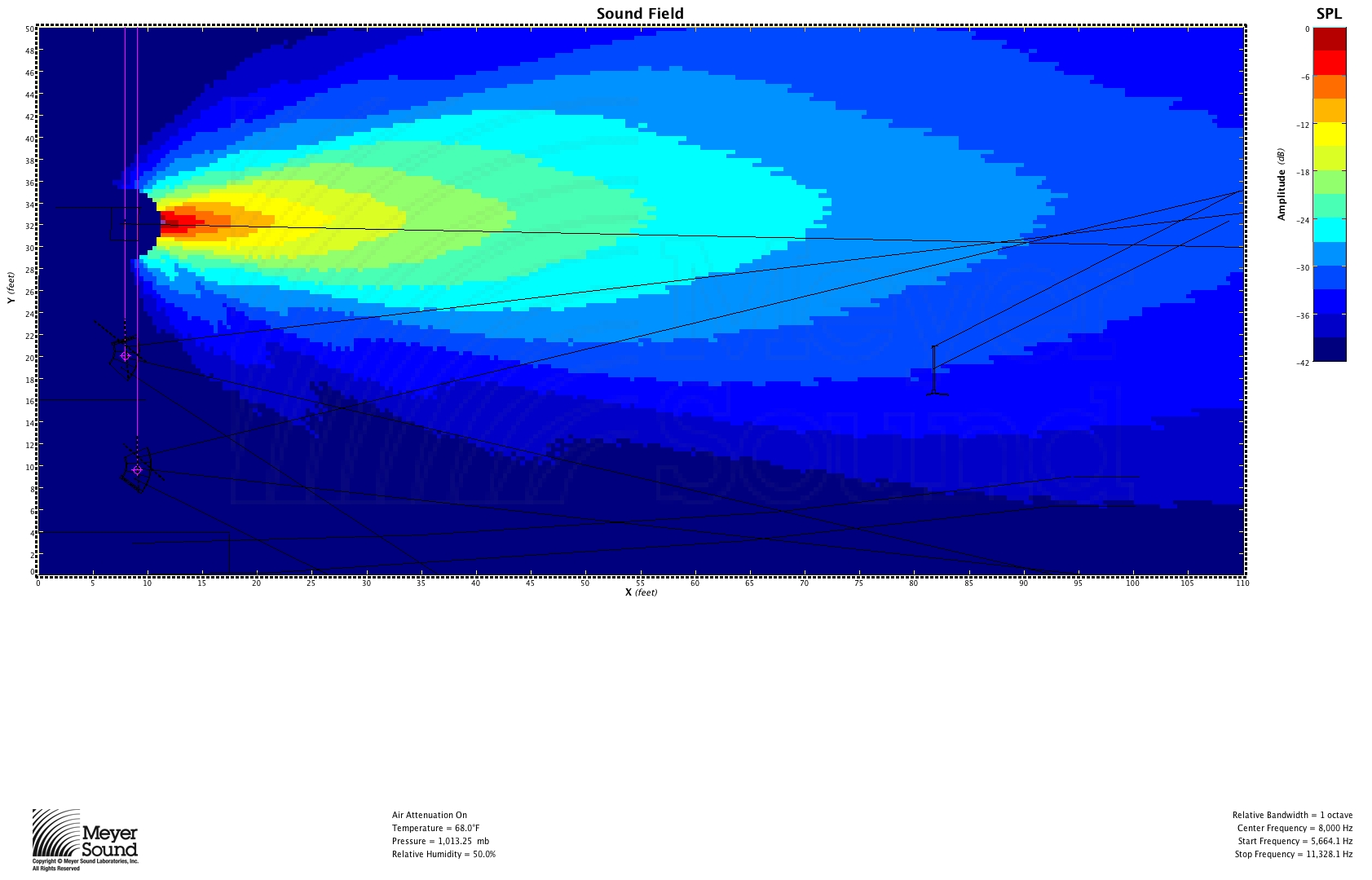
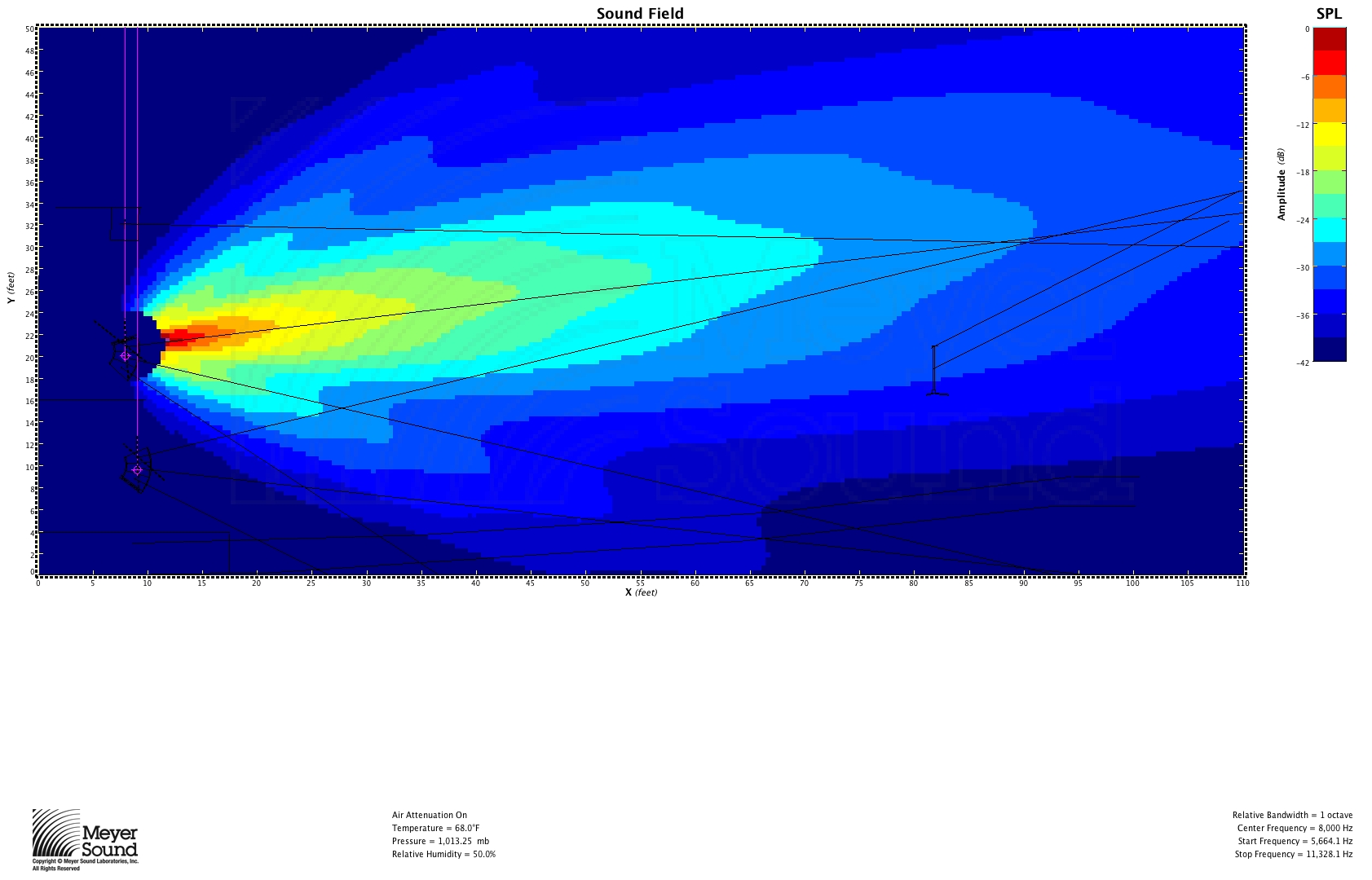
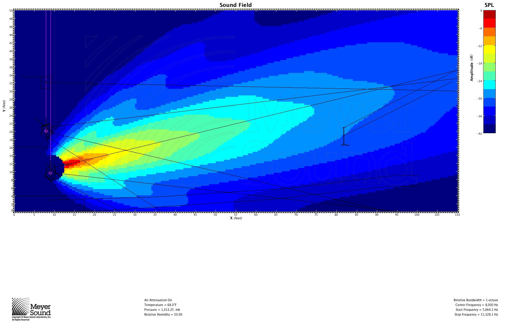
Also note that because of the substantial amount of energy hitting the back wall with a speaker pointed at the rear of the plane, a speaker with a coverage angle just smaller than that indicated by the formula and aimed not quite at the back of the plane may be the best solution.
Am I correct in assuming that this system must always be flown at a height near the top of the listening area?
Good question. I have updated the post in an attempt to address this. For most applications with only one general audience area, in practice you’ll usually want to fly high; otherwise, not necessarily. The first added example is what you might encounter if ground stacking for a theatre with a balcony. Given that speaker position just above the stage, I plugged the variables into the formula and it told me I needed an 18˚ box. The result shown is using the 20˚ JM-1.
Daniel,
Really great stuff. It is exciting to see the trig behind the FAR concept. There are a couple things worth addressing briefly
1) This basic concept is applicable to the horizontal plane as well as the vertical shown here. Typically the amount of asymmetry (R1 length compared to R2 length) is far greater in the vertical plane. Notable, though that the horizontal plane would have an R2 going both up AND down (R2a & R2b) – with a symmetric shape yielding a matched pair of R2 values and the ratio going in favor of one of them as asymmetry increases. In the cases shown here, the upper side (R2 = 0) so the formula is set for the maximum asymmetry. In such cases, as noted here, the upper half of the speaker pattern is unused, and with that come the options of when it is best to subdivide (budget permitting). But fulll asymmetry is not always the case – even in the vertical plane – such as an opera house where it rakes up on the floor and then goes straight up.
Understood that you are not attempting a one-size-fits-all solution. The reason i bring this I have been working to find repeatable, explainable solutions to case of partial asymmetry.
2) You say this above “This formula is readily applied to an audience area that is one plane where R2 is less than half of R1, but in practice few audience areas meet this condition and therefore cannot be covered consistently with a single speaker. ” I am having trouble with this – it seems backwards to me. I find many more verticals where the depth (R1) is far greater than the height (R2- below the speaker to the listeners). Do I have my R1s and R2s mixed up?
Thanks,
6o6
Thank you. With 2 you’re absolutely correct; I typed the opposite of what I thought. I have since changed it.
I hadn’t given much thought to using this in the horizontal plane; there is no one size fits all solution (or if there is, it involves scary calculus). I suppose you could apply it there, but would that entail having R1 be to the back center and R2(s) being to the side front(s)? I will play around with it.
As far as dividing the system goes, one approach is to find the point on the plane where the distance R2 is just over half of R1, insert the designated speaker, and for the rest of the plane (the lower part) use your compensated unity splay method. Regarding not using the top half of the speaker’s coverage, it seems to be the way to get the most consistent results when the plane meets the criteria for this formula, and if the speaker is to be tilted downward from the top (as in cinema standards) or cover opera house balconies that are vertical, for instance, you’d have to resort to some trial and error in a prediction program.
Anyhow, I am really excited to hear your thoughts and appreciate that you read closely. Sorry for the late reply.
Regards,
DL
Hi Daniel,
Thanks for publishing this work. It would be cool to see a followup of your experience using it in the field. Especially since most examples show the speaker on axis with the most distant seating position. Once you find out, let me know so I can publish a blog entry that says, “Research shows: Always point the speaker at the back!” 🙂
Thanks!
Nathan
Nathan,
Thanks for stopping by. I’ve been neglecting this blog (particularly my line array post) due to work, but I have some stuff on which I’ve been working that I’ll get up here soon. Regarding field work, I have used this for a center cluster to cover the distance from where the front fill were useless to where the mains came in (see uncoupled array ramblings for more on this), and on another gig where we had a ring of delay UPAs as in the example. I have not encountered a room where I could get decent results using only one speaker since deriving this, but experience has taught us that if it works in MAPP, it probably does in real life, too ;-).
All of the examples are pointed at the most distant seating position logically: the back will have the most distance attenuation but the least angular attenuation; the front will have little distance attenuation but much angular attenuation. Just be weary of rear-wall reflections.
I look forward to reading your blog entry.
DL
Finally got to use this on a project. Took me a while to figure out how to put sin-1 into a calculator!
I wrote about it here: http://www.nathanlively.com/2011/03/finding-speaker-coverage-in-one-step.html